 cad-agent.
Process profiles in code: minimum features and sheet-metal bends
A part is made by a process, and the process sets its limits: how thin a printed wall can be, how far a bridge can span, how short a bent flange can be. Those limits used to live as numbers typed into each tool. Now they are read from one cited file, research/process-profiles.yaml: 377 rules from bureaus, makers and textbooks for FDM, SLA, SLS, MJF, moulding, sheet metal and CNC, each with its source. Three modules read it. A rule from a design guide says a part is likely to be made well. It does not prove that it fits or holds.
| Module | What it does | What it reads |
|---|---|---|
cadagent.manufacturing.process |
Loads the profiles as typed values: rules, limits, tolerances, FDM layer factors, a shop's bend table. Every value carries its rule id and source id | the YAML; the data sheets in cadagent.mechanical.compliant.allowables |
cadagent.manufacturing.dfm |
The check. Holds walls, holes, pins, gaps, bridges, overhangs, flanges and hole-to-bend distances against every verified source, and says which way a printed feature's stress crosses the layers | the rules by compare key; the material's layer factors |
cadagent.manufacturing.sheet_metal |
The calculator. K-factor, bend allowance and deduction, flat length, shortest flange and relief | the shop's table first, then the generic rules and the bend-allowance formula |
cadagent.manufacturing.fit_coupons |
Its hole undersize and fit allowances are now read from the profile by rule id, not typed in | fdm-hole-undersize-cnckitchen, fdm-clearance-* |
The check: every source, side by side
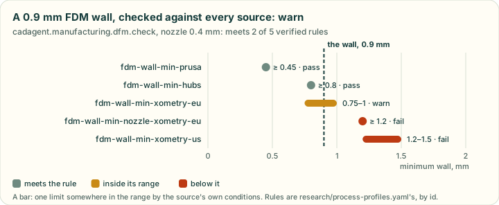
Drawn by tools/process_figures.py from cadagent.manufacturing.dfm.check on a worked example: a 0.9 mm FDM wall,
0.4 mm nozzle. Each row is one rule from the profile, coloured by its verdict.
Sources disagree. Prusa prints a 0.45 mm wall from a single 0.4 mm extrusion, while Xometry's industrial machines ask
for 1.2 mm. So dfm.check keeps every source rather than choosing one. A feature passes when it meets every
verified rule. It fails when it is beyond every verified rule, so no source would accept it. Anything between is a
warn that names the rules it does not fully meet. A rule with a range ("0.75 mm supported, 1.0 mm unsupported")
passes above its strict end and warns inside it, because the source's own conditions decide. Each rule's applies text (machine, material, part size) comes with it.
from cadagent.manufacturing import dfm
r = dfm.check("fdm", [dfm.Feature("lid wall", "wall", 0.9),
                      dfm.Feature("vent roof", "bridge", 8.0),
                      dfm.Feature("latch arm", "wall", 1.6, stress_dir=(0, 0, 1), flexes=True)],
              material="petg-bambu-basic", nozzle_mm=0.4)
r["verdict"]                      # "fail": the 8 mm bridge is over both sources' 5 mm
[(f["name"], f["verdict"], f["detail"]) for f in r["features"]]
Unverified rows. A rule whose status is u has not been read in its source. Today that is one row,
sls-gap-vs-wall-eos, which was read off a chart. The check lists such a rule as advisory with (u) after it, and
it never passes or fails a part on it. Profile.verified_rule() refuses one, for code that would enforce it.
Which way the layers run
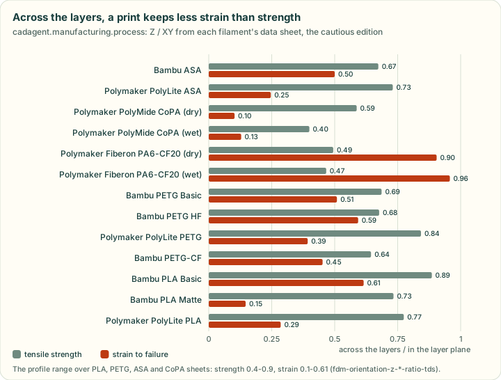
Drawn by tools/process_figures.py from cadagent.manufacturing.process. These are Z / XY ratios from each
filament's data sheet, taking the edition with the lower ratio. The values come from data sheets, not from coupons
printed here.
A printed part is weaker across its layers. It loses much more strain to failure than strength, so a snap arm that
bends across the layers breaks first. Give a feature stress_dir, the direction its bending or pulling stress runs
in the part's frame, and give build, the layer normal (default +Z). The check then says whether the stress crosses
the layers (more than 10° out of the layer plane). Across the layers, it gives the material's strength and strain
factors with the data sheet they came from. A feature marked flexes warns there: lay it in the layer plane, or size
it to the across-layer allowables (cadagent.mechanical.compliant.allowables).
The FDM materials come from the data sheets that allowables already holds, so the numbers live in one place:
PETG, PLA, ASA, CoPA, PETG-CF and PA6-CF, in 13 entries. Their source ids, such as bambu-petg-basic-tds, are the
reference registry's (#118). Until research/references.yaml is on dev, those ids do not resolve, and each factor
cites its sheet's own link.
The calculator: sheet-metal bends
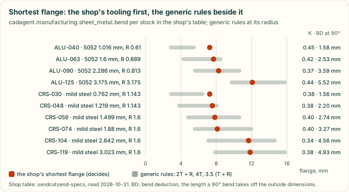
Drawn by tools/process_figures.py from cadagent.manufacturing.sheet_metal.bend for every stock in the shop's
table (sendcutsend-specs, read 2026-10-31). The generic rules are evaluated at the shop's own radius.
sheet_metal.bend reads the numbers in the order the profile asks:
- a value you give;
- the shop's row for the material and thickness: its radius, its K, its shortest flange and its relief depth;
- the generic rules.
Under the generic rules, the inside radius is the largest verified minimum (T for 5052 and mild steel). K comes from Protolabs Network's air-bending table, by hardness class and R / T. The flange and relief take the strictest verified rule, and every rule is listed with it. A radius other than the shop's drops the shop's K and flange, because those belong to its tooling.
from cadagent.manufacturing import sheet_metal as sm
b = sm.bend("5052", 1.6)            # SendCutSend ALU-063: R 0.889, K 0.42, shortest flange 7.696 mm
b["allowance_mm"], b["deduction_mm"]  # 2.452, 2.526 mm at 90 degrees
sm.flat_length([20, 30, 20], "mild-steel", 1.499)   # a U channel: 70 mm less two bend deductions
The equations: bend allowance BA = π (R + K T) A / 180 (the profile's formula sm-bend-allowance, from
SolidWorks' K-factor page). Outside setback OSSB = (R + T) tan(A / 2). Bend deduction BD = 2 OSSB − BA, the length
a bend takes off the sum of the legs measured to the outside. The tests check them against vectors worked by hand
(tests/test_sheet_metal.py).
This calculator gives a bend's numbers; it does not unfold a model. Unfolding a 3D part into its flat pattern is the
job of build123d's BuildSheet and unfold (to adopt once released) or FreeCAD's SheetMetal workbench, which take
the same K-factor and radius (the survey).
Feature kinds the check knows, and the limits it states
| Kind | Limit | Rules it reads |
|---|---|---|
wall, hole, pin |
at least | compare: min-wall, min-hole (sm-hole-min for sheet), min-pin; for FDM also fdm-wall-min-nozzle-xometry-eu (three nozzle widths) |
gap |
at least (a fit's band at its lower end) | compare: clearance-fit, and clearance rules with no compare key |
rib, slot, text |
at least | the FDM rib and text rules, the SLA slot rule |
bridge, overhang |
at most | bridge-max; overhang-max (FDM, degrees from vertical) |
flange, bend-radius, relief-depth |
at least (the shop's row decides) | sm-flange-min, sm-bend-radius-min, sm-relief-depth |
hole-to-bend, slot-to-bend, hole-to-edge, hole-spacing, relief-width, hem |
at least | the sm-* compare keys |
Limits, stated in every report:
- These are published rules for typical machines and settings, not measurements of your printer or shop. A rule's
appliestext is shown, not parsed. Passexclude=[...]for rules that do not apply, and record why. - Sizes are what you declare.
dfmdoes not measure a model;cadagent.review.gates.wallmeasures walls by rays. - K depends on the lot, the tooling and the method (air bending here). The flat length is a starting blank, and the shop's CAD or a test bend sets the final one. Most sources do not state the datum their minimum flange is measured from. Cracking at a tight radius, a hard temper or a bend across the grain is not predicted.
- The data file is read from the cad-agent checkout the package runs from. Set
CADAGENT_PROCESS_PROFILESto use another copy.
Related
Process profiles: the sources · Printed joints and fit coupons · FDM anisotropy data · Manufacturing package